GPIO (General-Purpose Input/Output) is a crucial component for interfacing the MCU with the outside world.
What is GPIO? #
A pin on a MUC can be programmed to function as either an input or an output, such as receiving signal from sensors as an input or blinking a LED as an output.
Features #
- Configurable: Each GPIO pin can be configured as input or output ib different application;
- Simple Digital Communication: GPIO pins operate with simple digital logic (HIGH or LOW states);
Pin Consideration #
GPIO Output Modes #
Push-Pull Mode: In Push-Pull mode, the GPIO pin actively drives the output to both HIGH and LOW states by connecting it to either the supply voltage or ground as needed. This mode is ideal for applications like LEDs and fast digital communications (e.g., SPI) where strong, stable signals are required. However, it’s not suitable for lines shared by multiple devices, as conflicts may arise if more than one device tries to drive the line simultaneously. Similar as a INV in CMOS.
Open-Drain Mode: Open-Drain mode only drives the pin LOW, requiring an external pull-up resistor to reach a HIGH state. This mode is commonly used for shared communication lines like I2C or shared interrupt lines, allowing multiple devices to use the same line safely without interference. The need for a pull-up resistor, however, may slow signal transitions, making it slightly less responsive than Push-Pull.
GPIO Input Modes #
Floating (High Impedance): In floating mode, the GPIO pin is in a high-impedance state with no default voltage level, making it sensitive to external signals. This mode is useful when an external circuit fully controls the voltage, such as with digital sensors. However, without a defined state, the pin can pick up noise, leading to erratic input values.
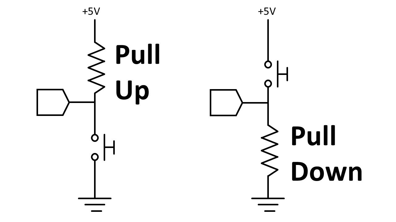
Input with Pull-Up: An input pin with a pull-up resistor defaults to a HIGH state, making it suitable for applications like button detection, where the pin should stay HIGH when unpressed. This setup prevents floating values but may interfere if the circuit needs a reliable LOW state.
Input with Pull-Down: An input pin with a pull-down resistor defaults to a LOW state, keeping the input stable when not driven. This mode is often used for external signals that occasionally need to pull the pin HIGH. However, it can cause issues if the circuit requires the pin to default to HIGH instead.
Pull-up/Pull-down Resistors:
- When configured with pull up resistor, active low.
- When configured with pull down resistor, active high.
Summary Table #
| Mode | Type | Description | Common Applications |
|---|---|---|---|
| Push-Pull | Output | Actively drives both HIGH and LOW states | LEDs, digital communication lines |
| Open-Drain | Output | Drives LOW only, requires pull-up for HIGH | I2C, shared interrupt lines |
| Floating (High-Z) | Input | High-impedance, no default state | Sensors, external control |
| Pull-Up Input | Input | Held at HIGH by internal pull-up resistor | Button inputs, stable HIGH default |
| Pull-Down Input | Input | Held at LOW by internal pull-down resistor | Detect external high signal inputs |
P.S. Interrupts: Some GPIO pins can be configured to trigger interrupts, allowing the system to respond immediately when an external event occurs (e.g., a button press).